
 EN
EN  NL
NL  DE
DE  FR
FR 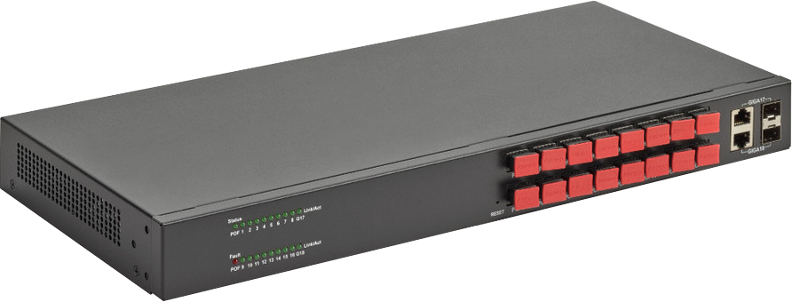
manual
Optolux® Distribution Switch 16
OXS-M64-EU


Manual
Optolux® Distribution Switch 16
OXS-M64-EU
Index
About the product
The Optolux® Distribution Switch 16 is a layer 2 managed network switch that provides sixteen Gigabit Easy Lock™ ports for Polymer Optical Fiber (POF) connections, and additionally two RJ45/SFP Gigabit Ethernet combo ports to connect to traditional cable media.
The internal high speed network processor can manage all network traffic between the ports, and offers all generally used network management functionalities.
Its 1U metal housing with all network connections on the front side, in combination with the internal power supply, allows for very easy mounting in 19″ racks. This makes it very suitable for application in business/IT environment.
Access to all network management functionalities is provided via either a GUI on an internal web interface, or via the debug port on the backside.
What is in the box?
| Quantity | Item | Product nr |
|---|---|---|
| 1 | Optolux® Distribution Switch 16 | OXS-M64-EU |
| 1 | AC power cord | |
| 1 | Rack-mount kit for 19” rack installation | |
| 1 | Installation manual |
Warnings & Precautions
Please read the following warnings and precautions carefully.
Remove power from power line
Make sure and verify that the power running towards the device is OFF before installing the device.
Tip: Switch off the phase you are working with.
Do not stare into POF ports & POF cables
Refrain from looking directly into the POF ports or the ends of the POF cable. The used optics emit a red color so you can see the light in order to establish the correct way of installing the cables. The red light is LED based and not harmful. However, staring into the light for a prolonged period can result in eye irritations or worse.
Use the proper tools for installation
When installing the devices make sure to use proper tools that are purpose made for the job at hand. Using the wrong tools may result in injury.
Never insert tools and materials that are conductive into the device
You may get an electrical shock when inserting tools and materials that are conductive into the device. Please refrain from using such tools and materials for these purposes.
Follow construction regulations
For your own personal safety always follow the construction warnings and regulations when installing the device.
Do not open the device
By opening the device all warrantee’s and guarantees will terminate.
Other
- Work on the electrical parts of the device must be performed by a certified professional.
- Only use the device for its intended purpose.
- Only install the device following the instructions provided in this manual.
- Refrain from manipulating, altering, adjusting the device in any way other than as indicated in this manual. This includes but is not limited to heating the device, deforming it in any way, applying lubricants and using excessive force.
- Operate the device in its intended environment and within its environmental conditions.
Product overview
Frontside

Backside

Connect the switch
Installation
Step 1
Connect the power cord to the backside of the switch and plug the power cord into the mains.
Step 2
Turn the switch on using the ON/OFF switch on the backside. The Status LED will turn on, indicating power.
Step 3
The switch will now boot with default settings and configuration.
Step 4
Connect the switch to your network. This can be done from any port but is typically done via one of the RJ45 or SFP ports. Note that each RJ45/SFP is a dual port acts as 1 logical port.
Step 5
Observe from the LED that corresponds with the port that has been used, that the connection to the
network has been established.
Step 6
Now further devices can be connected to the switch, via the Easy Lock™ ports, or the RJ45/SFP dual port terminals.
Step 7
The switch will automatically create a link to each connected device.
Configure the switch
In the default setting, the switch has a fixed IP address. In order to configure the switch, you need to connect a computer to one of the ports of the switch.
Initial setup
Step 1
Change the IP address of the connected computer, and assign it with an IP address in the range 192.168.0.xxx (this is the same range as the IP address of the switch).
Step 2
Enter the default IP address of the switch in any browser that is available on your computer. 192.168.0.24
Step 3
Login with the default login data on the configuration interface of the switch: USER: admin
Password:
Step 4
Configure the switch for your network. For security reasons, it is advised to change the login data into secure login data that will be known only to authorized persons.
Step 5
More information for configuration options via the web interface can be found in the manual, available at: www.fiberunlimited.com/manuals
Troubleshooting
In case you encounter problems in working with the switch, here are some suggestions to find the cause and this.
- Check if all cables are connected properly; verify that the POF cable that shows the red light, is connected to the Easy Lock™ hole that is dark (and vice versa).
For every activated device that is connected to any port of the switch, the corresponding status LED of the connected port will be lit. - For Easy Lock™ ports, make sure that all POF cables are properly cut (straight, no residues) and fully pushed into the Easy Lock™ port (it needs to go approx. 20mm into the terminal). Don’t forget to do the same check on the side of the connected device.
- For Easy Lock™ ports, verify that there is no residue inside the port that can block the light. Make sure to check both sides (the transmitter as well as the receiver) of the Easy Lock™.
- Make sure that the network settings of the computer are correct (fixed IP or DHCP client, correct IP range).
In most cases, computers are configured to obtain an IP address through DHCP. If the network uses static IP addresses, be sure that the switch and computer are configured with valid IP addresses. - To connect to the web interface of the switch, the IP address of the computer has to be in the same subnet as the switch (e.g. switch: 192.168.0.xxx, computer: 192.168.0.xxx)
- Make sure that VLAN settings are correct. VLAN on an outgoing port of the switch needs to have also that same VLAN on the incoming port of the switch (router side).
Support
More information
For more information, you can check our website www.fiberunlimited.com or the manuals at www.fiberunlimited.com/manuals.
Personal support
If you are in need of personal support please sent your question to support@fiberunlimited.com.
Required information
Please include both the product ID, Mac-address and/or serial number (on the top side of the device) in your inquiry. This will help give you the support you need.
Declaration of conformity
We, FiberUnlimited declare under our sole responsibility that this device is in conformity with the essential requirements and relevant regulations of the applicable EU-directives (2014/30/EU, 2014/35/EU, 2011/65/EU). The complete Declaration of Conformity is available in the download section at www.fiberunlimited.com.
Disposal & Recycle
Guideline 2002/96/CE concerning the handling, collection, recycling and disposal for electrical and electronic equipment and their components („waste electrical and electronic equipment“, known as WEEE). The crossed symbol on a rubbish container indicates that the machine or device is not allowed to be disposed of but it must be handed over to a suitably equipped collection center for proper recycling or disposal.
Disclaimer
Information regarding this product is subject to change without notice.
All information in this publication generally reflects the status at the time of printing. Despite considerable care taken in the preparation of the publication, errors may occur. We also reserve the right to make changes to our products, specifications and other data. Changes may also become necessary as a result of legal, technological or other external requirements, which canno t or can no longer be considered in this publication.
For this reason, we cannot assume any liability which is based solely on the data provided in this publication. The decisive role with regard to the data on products and services is always played by the order placed, the product actually purchased and the documentation in connection with it, or the information provided by our specialist staff in each specific individual case.